




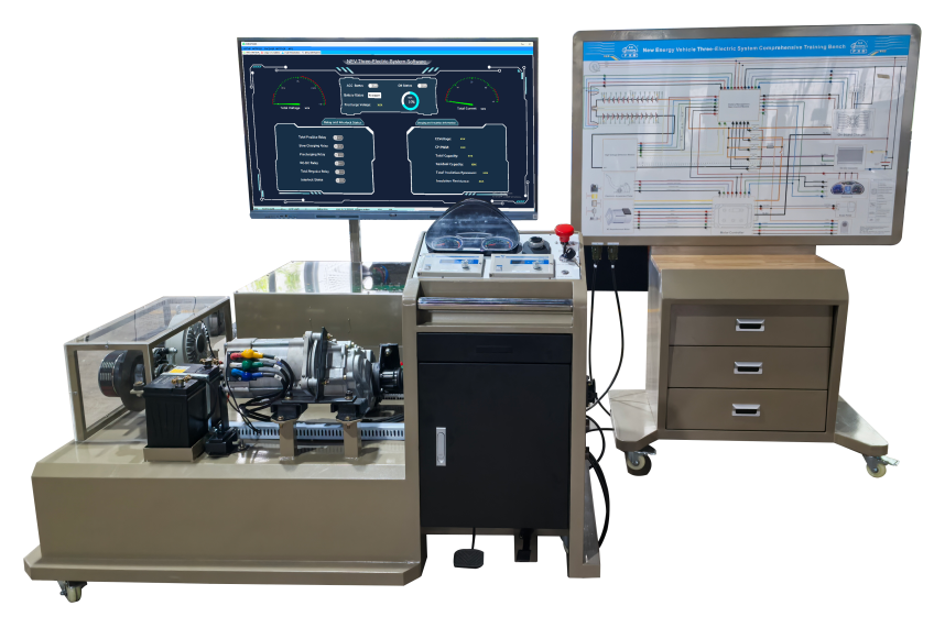
This product requires the use of a 76.8V new energy power battery pack, a distributed battery management system, and the power battery pack control method is the same as the actual vehicle; the power battery pack outputs 76.8V high-voltage DC, the operating platform and the detection platform are separated, and aviation connectors are used for connection, and real-time data is measured on the measurement platform; through hands-on connection and original vehicle part detection by students, the working principle and circuit connection of the core components of the new energy power battery system, as well as the connection control relationship, installation location and operating parameters between the components, are mastered during the practical operation; the equipment functions and control methods are exactly the same as those of new energy low-speed electric vehicles, focusing on cultivating students' hands-on ability and fault analysis ability.
II. Completable Practical Training Projects
1. Understand the assembly and connection methods of lithium iron phosphate power battery pack
2. Learn the basic parameter measurement methods of lithium iron phosphate power battery pack
3. Master the common fault judgment and repair methods of lithium iron phosphate power battery pack
4. Understand the internal structure and basic parameters of high-voltage and high-current relays
5. Learn the basic parameter measurement methods of high-voltage and high-current relays
6. Master the common faults and replacement methods of high-voltage and high-current relays
7. Learn the basic parameter measurement methods of Hall current sensors;
8. Master the common faults and replacement methods of Hall current sensors;
9. Understand the role of manual maintenance switches in high-voltage circuits;
10. Understand the protective role of high-voltage interlocks;
11. Understand the working principle and pin definition of on-board chargers;
12. Master the common faults and replacement methods of on-board chargers;
13. Understand the working principle and pin definition of DC-DC converters;
14. Master the DC-DC Common faults and replacement methods of conversion;
15. Understand the control method and composition of distributed battery management system;
16. Understand the composition and function of AC asynchronous motor parts;
17. Master the insulation performance detection method of power battery and high-voltage connecting wire;
18. Master the control parameter measurement method of AC asynchronous motor drive system;
19. Master the common faults and troubleshooting methods of AC asynchronous motor drive system;
20. Understand the working principle and pin definition of electronic throttle pedal;
21. Master the common faults and replacement methods of electronic throttle pedal;
22. Understand the working principle and pin definition of AC asynchronous motor;
23. Master the common faults and replacement methods of AC asynchronous motor;
24. Understand the working principle and pin definition of electric vacuum pump;
25. Master the common faults and replacement methods of electric vacuum pump;
26. Understand the working principle and pin definition of pressure sensor module;
27. Master the common faults and replacement methods of pressure sensor module.
III. Product Function Requirements
1. The power battery pack is required to be composed of lithium iron phosphate power batteries, with a single battery of no less than 3.2V52Ah, and no less than 24 batteries connected in series. The power battery pack capacity is required to be no less than 76.8V52AH, and the number of full charge and discharge times is no less than 2000 times; the operating temperature is between -20℃ and 60℃; it is required to adopt a distributed battery management system, 1 acquisition module, which is responsible for the information acquisition of 24 single batteries, and 1 main control module, which communicates with the acquisition module through the CAN network; the power battery pack is used as a basic configuration to output high voltage electricity to different electric drive system training benches, so that students can master the most advanced power battery PACK technology.
2. The power battery pack is equipped with a detection port, which can measure the voltage of single batteries and battery PACK; the discharge relay, charging relay, pre-charge relay, and Hall current sensor are equipped with detection ports, which can measure the on and off of the control power supply; so that students can master the detection ability of real vehicle parts.
3. The touch-integrated device has built-in embedded new energy vehicle BMS host computer teaching software V1.0; the power battery pack BMS battery management system information is displayed on the touch-integrated device display screen through CAN communication, and can display the real-time voltage of each power battery, the real-time temperature of multiple monitoring points, the working status of the discharge relay, the working status of the charging relay, the working status of the DC-DC relay, the high-voltage interlocking status and other battery pack information in pages; intuitively grasp the changes in the internal parameters of the power battery;
4. The power battery pack is equipped with a high-voltage circuit mechanical maintenance switch to facilitate cutting off the entire power supply.
5. The mechanical maintenance switch, power battery output interface, and power battery charging interface are all equipped with high-voltage interlocking circuits to ensure the safety of the high-voltage interface if it is not installed properly and not powered on.
6. The training platform is equipped with an emergency power-off switch. The emergency power-off switch is installed in an easy-to-operate position at the front of the power battery pack. In an emergency, press the red emergency power-off switch button to cut off the power of the entire high-voltage power system to ensure the safety of the teaching process.
7. The power battery pack is translucent in design and has built-in LED row lights for students to observe the internal structure of the battery.
8. The training platform is equipped with a mainstream pure electric vehicle single-speed gearbox, front floating drive shaft, and brake assembly; the brake assembly drives the real load device through flexible transmission, and the load size can be adjusted separately to reproduce the actual working conditions of the vehicle going downhill, driving on flat roads, driving uphill, starting on a half-slope, and turning; so that students can master the laws of current and voltage parameter changes under actual working conditions.
9. The training platform is equipped with a pure electric vehicle electric vacuum booster system to make braking operation easier. The vacuum tank is a full stainless steel structure, and the pressure sensing switch is a sensor structure with a service life of more than 100,000 times.
10. The training platform is equipped with a 12V power grounding mechanical switch, which can disconnect the 12V grounding at any time to cut off the power supply of the entire system. The auxiliary battery voltage capacity is 12V45AH.
11. Four casters are installed at the bottom of the training platform, which is flexible to move. At the same time, the casters are equipped with self-locking devices, and the installation position can be fixed at will.
12. The base of the training platform is welded with alloy steel structure, which is strong and shockproof; protective devices are installed on both sides to ensure safety during use.
13. The training platform is equipped with an aluminum alloy teaching board, which clearly marks the composition and control principle of the power battery pack. The teaching board material is 4mm fully conductive aluminum-plastic board, and the drawing is laser sprayed, which will never change color; the teaching board is installed with detection terminals and with the help of multi-meters and oscilloscopes, parameter changes under various states can be detected in real time.
14. The power battery pack of the training platform is equipped with a real car fault protection device. By disconnecting the line in situ, the power battery pack can be set internally. There are no less than 10 fault points, including high-voltage interlocking circuit breaker, total positive relay control signal circuit breaker, pre-charge relay control signal circuit breaker, charging relay control signal circuit breaker, BMS slave control module 1 power circuit breaker, BMS slave control module 2 CAN signal circuit breaker, high-voltage detection module CANH signal circuit breaker, main control module ON signal circuit breaker, AC charging CAN signal circuit breaker, AC charging CC signal circuit breaker.
15. The training platform is also equipped with a DS2019-29 automotive clamp meter and a DS2019-28 high-voltage test pen, which are used to control the line voltage, current and other parameter measurements and the contactless measurement of orange high-voltage circuit high current.
IV. Technical Parameter Requirements
1. Dimensions of the main part (mm): not less than 1650*1450*1720 (length*width*height)
Dimensions of the detection part (mm): not less than 1400*640*1750 (length*width*height)
Height of the detection part table (mm): 810±10
Drawers of the detection part: not less than 3 layers
2. Equipment working power supply: AC220V±10% 50Hz, power not more than 2KW
Equipment working temperature: -20℃~+40℃
3. Auxiliary battery: not less than 12V45AH
4. Power battery type: environmentally friendly lithium iron phosphate power battery (square aluminum shell, single cell 3.2V52AH)
Power battery pack capacity: 76.8V52AH
Full charge and discharge times: 2000 times
Working temperature: -20℃~60℃
5. AC asynchronous motor drive system
Rated power: 5KW
Peak power: 10KW
DC bus rated voltage: 72VDC
Rated torque: 16Nm
Rated speed: 3000r/min
Maximum speed: 5200r/min
Protection level: IP54
Cooling method: natural air cooling
Gearbox:
Two-stage helical gear transmission, total reduction ratio 1:16.7;
7. Load device (2 sets):
Magnetic powder brake: PBS-50 (with adjustable tension controller)
Rated torque: 50N.m
Permissible speed: 1500r/min
Flexible multi-V belt: 10PK-1100
8. Touch integrated device
CPU: Not less than I7-10 generation
Memory: not less than 16G
Hard disk: not less than 512G solid state hard disk
Screen size: not less than 55 inches
Touch type: capacitive touch
V. Basic Configuration Requirements
1. 1 set of lithium iron phosphate power battery pack (including 24 single cells, 1 total positive relay, 1 total negative relay, 1 charging relay, 1 pre-charge relay, 1 DC/DC relay, 1 pre-charge resistor, 1 high-voltage detection module, 1 set of mechanical maintenance switch, 1 set of charging interface, 1 set of discharge interface, 1 low-voltage control interface, 2 power battery acquisition modules, 2 BMS slave control modules, 1 BMS battery management system master control module)
2. 1 on-board charger (CAN communication)
3. 1 7-core standard charging interface (with CC/CP signal)
4. 1 220V standard charging gun
5. 1 DC-DC converter ;
6. 1 motor controller
7. 1 electronic throttle assembly;
8. 1 shift mechanism assembly;
9. 1 set of high-voltage wiring harness;
10. 1 AC asynchronous motor;
11. 1 combination instrument (with CAN communication);
12. 1 gearbox;
13. 2 drive shafts;
14. 2 front wheel disc brakes;
15. 2 flexible multi-V belts;
16. 2 magnetic powder brakes;
17. Manual tension control 2 devices;
18. 1 vacuum pump assembly;
19. 1 vacuum tank assembly;
20. 1 auxiliary battery;
21. 1 mechanical battery power-off switch;
22. 1 DS2019-29 automotive clamp meter;
23. 1 DS2019-28 high-voltage test pen;
24. 1 movable training platform;
25. 1 movable detection teaching board;
26. 1 booster pump assembly.
27. 1 touch integrated device
VI. Supporting Teaching Resource Package Software.
The requirements are as follows
1. Based on the comprehensive training platform for the three-electric system of new energy vehicles, the structure is displayed in a three-dimensional model, which is clearer and more beautiful than the real object. The position, connection method, structure, etc. of each component are displayed in multiple directions, which is consistent with the real object, making it easy to teach outside the training room.
2. Divided into four parts: overall structure, operation steps, structural principle, and circuit measurement.
3. Overall structure, no less than 4 perspectives, divided into: reset, top view, left view, right view, all-round display of the bench structure, clearly display the structure, position, and connection relationship of each component, each component can be clicked to display the introduction, which is convenient for preliminary teaching or overall quick review. In addition, there is a "detailed explanation" button below the introduction link, which can quickly connect to the third part of the structural principle, the detailed knowledge module of the component, so that students can learn from the bench and the course.
4. Operation steps, no less than 5 3D animation operation videos: including equipment operation method, equipment charging operation, current detection operation, fault setting (wireless device), battery pack voltage detection;
This module uses animation to explain in detail the main operation methods of the bench, precautions, and key steps of the operation are accompanied by text explanations to prevent students from not knowing how to operate or misoperating. Through the display of animation, students can quickly get started with the use of the bench.
5. Structural principle, Module 3 is one of the key points of course learning. This module explains in detail the structural composition and working principle of each component, covering all components of the test bench, no less than 16 components.
5.1. Power battery pack
Includes the role of power batteries, battery types, single battery structure, main process of battery cell manufacturing, power battery charging and discharging principles, and battery performance testing.
5.2. Battery management system
Includes the importance, classification, BMS architecture, BMS functions, BMS external drawings, and BMS control process of battery management systems.
5.3, High-voltage interlock
5.4, Charging port
5.5, On-board charger
5.6, DC-DC converter
5.7, Battery
5.8, Motor controller
5.9, Shift lever
5.10, Accelerator pedal
5.11, Electric vacuum brake system
5.12, Drive motor
5.13, Transmission assembly
6. Circuit measurement
6.1, Through dynamic flow chart, virtual demonstration of the circuit dynamics of the test bench under different working conditions, so that students can learn the circuit and signal transmission method more intuitively. The circuit measurement page can be zoomed in and out, which is convenient for users to view the circuit more clearly;
6.2, The right side is the control panel, the control sequence is the same as the actual test bench, for example, it cannot be charged in the driving state, and the operation function is the same as the test bench, which is convenient for students to learn the circuit of the test bench. There are eight operation buttons: main power switch, ignition switch (3 states), gear (3 states), acceleration (4 states), load (4 states), brake, charge, and maintenance switch. All normal working states of the test bench can be simulated.
6.3 Signal measurement: This page contains a large number of measurement points, each of which will change accordingly according to the change of the state.
7. Basic configuration: 1 USB flash drive, 1 dongle, 1 packaging box, 1 manual; no need to install software, generally the computer can play by plugging in the USB flash drive and dongle;