


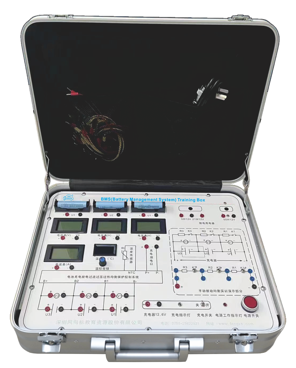
The BMS(battery management system) training box simulates the working conditions of the high-voltage battery management system under low voltage conditions: mainly including overcharge protection in the charging state, over-discharge protection in the discharging state, over-current protection in the charging and discharging state, high temperature protection, passive balancing demonstration in the charging state, etc.
II. Features
1. Charging experiment: When the battery voltage is low to a certain level, the battery needs to be charged. The system is equipped with a charger.
2. Discharging experiment: In order to reduce the voltage of the battery pack and conduct relevant experiments, the system is equipped with discharge electrical appliances of different powers.
3. Voltmeter: used to monitor the voltage changes of each single cell in the battery pack during the charging and discharging process.
4. Ammeter: used to monitor the changes in the magnitude and direction of thecircuit current during the charging and discharging process.
5. Thermometer: used to simulate and display the temperature changes of the battery pack and provide data support for high temperature protection of the battery pack.
6. Power working indicator light: indicates whether the system is connected or disconnected from 220V AC.
7.Charging indicator light:
1) The red indicator light is on while charging.
2) Red and green flash alternately in passive balance.
3) The green indicator light turns on when charging is complete.
8. Power switch: connect or disconnect the 220V AC power supply to the system.
9. Battery rack: used to install and fix single cells for experiments.
10.18650 battery: used to form a battery pack and perform various experiments.
11.Battery Management:
1) Overcharging protection - For a battery pack consisting of three 3.7V lithium-ion batteries connected in series, the total charging voltage of the battery pack should not exceed 12.6V. When the charging voltage reaches or approaches 12.6V, the control board will automatically disconnect the battery pack and the charger. At this time,
the charging indicator light changes from red to red and green flashing alternately until it turns green, and charging is completed.
2) Over-discharging protection - For a battery pack consisting of three 3.7V nominal voltage lithium-ion batteries connected in series, the total discharging voltage of the battery pack should not be lower than 9.6V (determined by the discharging power). When the discharging voltage reaches 9.6V, the control board will automatically disconnect the battery pack and the charger, causing the battery pack to cease operation and terminate the discharging.
3) Overcurrent protection - When a high-power discharger is selected or the output is short-circuited, the discharging current of the battery pack exceeds the maximum current set by the control board, the control system disconnects the output and performs necessary protection on the battery pack. If within the permitted power range, the normal discharging process of the electrical appliance will proceed.
4) High temperature protection: When the internal temperature of the battery pack reaches a certain value, it indicates that the battery pack is abnormal, so both charging and discharging must be stopped and the control board is automatically disconnected. Only when the temperature returns to normal can charging or discharging to be continued to protect the battery pack.
5) Passive balancing: During the charging process, when batteries with different voltage differentials are assembled into a battery pack, and the charging voltage of any single cell reaches 4.18V (ideal condition, actual values may vary), the control system activates the passive balancing function, connecting this 4.18V battery to the balancing resistor for discharging. The balancing resistor will heat up slightly because of the current passing through it. When the battery is discharged to a certain extent, the charging system will have charging current flowing through the single cells that have not been fully charged yet, enabling them to continue completing the charging process until full charging is achieved. At this point, the charging indicator light will be seen flashing alternately in red and green.
6) Manual demonstration of passive balancing process: Through the passive balancing principle circuit diagram on the panel, connect the battery, voltmeter, discharging resistor and control switch to fully demonstrate the process and working principle of passive balancing.
12.Self-recovery fuse: Provides protection for individual battery cells to prevent direct short-circuiting of the positive and negative terminals during experiments, which could cause battery damage.
13. Banana socket: By using different experimental connection wires for plugging, it can serve as instrument test terminals.
III. Basic Parameter
1. Dimensions: 435mmx325mmx200mm(length x width x height)
2. Approximate weight: about 4.5KG
3. Operating voltage: AC220V
4. Working temperature: -20℃ - +40℃
5. Working power: ≤100W